Service hotline
+86 0755-83044319
release time:2022-03-17Author source:SlkorBrowse:11230
Electrification and electrification of automobile power system is the only way to achieve carbon neutrality in the transportation field. As the world's first automobile semiconductor technology company, Infineon firmly believes in the view that "zero emission will be achieved" and is committed to promoting the early realization of this goal.
Here, "electrification" refers to the hybrid power system in which various modes of traditional internal combustion engines coexist with electric motors, while "electrification" refers to the electric drive power system that completely gets rid of the traditional internal combustion engines.In the process of "electrification" and "electrification" of automobiles, the paths chosen by various countries and regions, as well as various automobile manufacturers, are similar, but all roads lead to the same goal. This includes both micro-hybrid systems like 48V and full-hybrid and plug-in hybrid systems. It includes both pure electric vehicles using lithium-ion batteries as energy carriers and fuel cell vehicles using hydrogen as energy sources.
As we all know, a system can be abstracted into five parts: perception, calculation, execution, communication and power supply.This paper will put forward some personal views and thoughts on the two topics of power supply and execution in these five parts.。
一 、Power supply voltage track in vehicle power supply system
At present, what we can see in passenger cars are the power supply systems of 12V, 48V and high voltage (400V/800V).In traditional internal combustion engine passenger cars, 12V power supply has been used all the time, and the corresponding semiconductor products also occupy a large part of the market. According to the forecast information of some international authoritative organizations, cars driven solely by internal combustion engines will withdraw from the market around 2030. However, considering the scale advantage of the mature parts supply chain of 12V system and the relatively low cost advantage of semiconductor products suitable for the application of this system, the 12V power supply rail should exist for a long time. At that time, DC-DC will completely replace the traditional 12V alternator and become the power supply for battery charging and load power supply in 12V system, which will bring about some changes in the characteristics of 12V power supply system, such as load shedding.
As the corresponding power supply standard, it may be adjusted accordingly.48V, as a safe voltage class, has a certain cost-effective advantage in hybrid power system because of its lower insulation grade requirements and other factors. With the improvement of the supply chain in 48V system, the cost of large-scale production is reduced. At the same time, the standardization of some parts in different high-voltage vehicles helps suppliers and vehicle manufacturers to reduce the cost of parts management. In this way, the 48V power supply rail may be introduced not only in vehicles with micro-hybrid system, but also in new energy vehicles with high-voltage system, so that some medium-power loads (for example, between 1kW and 10kW) can run in the 48V power supply system, thus bringing the bright appearance of the application of DC-DC converter which converts high voltage (400V/800V) to 48V.
As three rails (HV, 48V, 12V) coexist in the same vehicle, considering the architecture, functional safety and cost of the whole vehicle, whether the power supply network topology uses centralized voltage conversion or distributed voltage conversion will depend on the design of the whole vehicle factory, and the power level and functional safety level of DC-DC will also have different requirements.
二、About "execution"
As mentioned above, the coexistence of three rails of power supply voltage leads to different requirements for actuators under different voltage rails, that is, different requirements for semiconductor power devices. Different voltage rails require different withstand voltage levels for semiconductor power devices. Different applications require different driving currents and different switching frequencies for power devices.
The 48V voltage track concentrates the application of power levels from 1kW to 10kW. Among them, DC-DC and motor inverter are the majority. Considering the withstand voltage and power level, this is the main battlefield of silicon-based MOSFET and GaN. However, at present, it will take some time for GaN to be applied in automotive electronics.
The following figure shows some corresponding application fields of silicon, silicon carbide and gallium nitride power devices for reference.
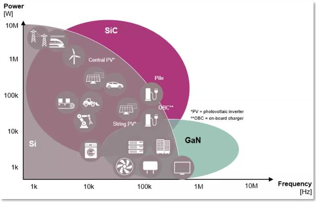
As for the power devices used in high-voltage rail, the hottest topic at present is silicon carbide (SiC). Silicon carbide power devices have the advantages of low switching loss, high withstand voltage, high working temperature and high heat dissipation capacity, so that the system can work at higher voltage and higher frequency, thus reducing the volume of passive components, reducing the power loss of the system and improving the power density of the system. However, on the other hand, the current devices made of silicon carbide have some disadvantages compared with those made of silicon. Based on the comprehensive results, we believe that silicon and silicon carbide power devices will coexist in the future for quite some time, giving full play to their respective strengths in their respective fields.
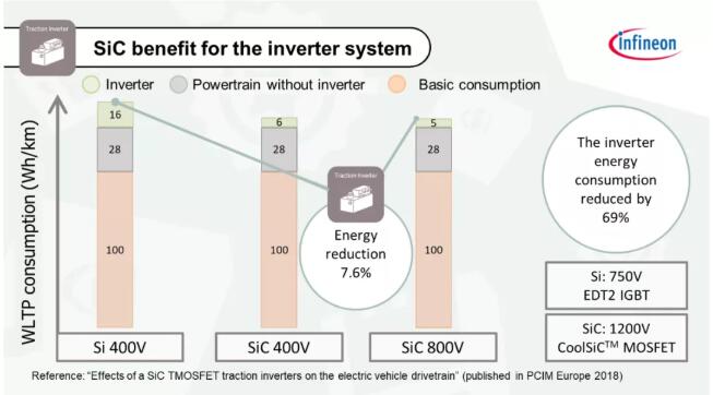
According to the analysis and test information of Infineon, the power system using silicon carbide devices can reduce the power loss by about 7.6% compared with the power system using silicon devices at the same power level, including the power loss reduction during motor driving and the power loss reduction during motor energy recovery.
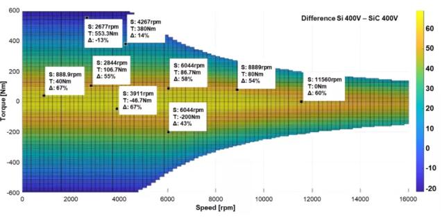
The following figure is a comparison of a set of experimental data of power device power consumption difference when the motor uses silicon-based IGBT and silicon carbide MOSFET at different rotational speeds and torques. It can be seen that when the motor speed is 2667rpm and the output torque is 553.3Nm, the power consumption of silicon-based IGBT is about 13% less than that of silicon carbide MOSFET.
From this, we can roughly get the application scenarios of silicon-based IGBT and silicon carbide MSOFET in driving inverter, as shown in the following figure:
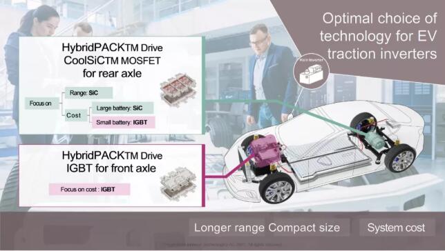
Adopting the "Hybrid" scheme shared by silicon-based IBGT and silicon carbide MOSFET can give full play to their respective advantages and learn from each other's strong points. The motor driven by silicon-based IGBT can give full play to the advantage of lower power loss than MOSFET under high current, mainly providing high torque output, reflecting the acceleration performance of the whole vehicle; However, the motor driven by silicon carbide MOSFET works more in cruising condition, which improves the energy utilization efficiency. So as to achieve both ends, and have both fish and bear's paw.
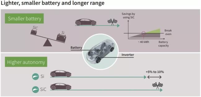
This can make the vehicle keep the same cruising range while reducing the battery capacity, thus reducing the battery cost, and make some compensation for the cost increase caused by the introduction of silicon carbide power devices. At the same time, the reduction of battery capacity and the increase of inverter power density can also reduce the weight of the vehicle and improve the energy utilization efficiency of the whole vehicle.
Disclaimer: This article is reproduced from "Infineon Automotive Electronics Ecosphere". This article only represents the author's personal views, and does not represent the views of Sacco Micro and the industry. It is only for reprinting and sharing to support the protection of intellectual property rights. Please indicate the original source and author when reprinting. If there is any infringement, please contact us to delete it.
Company Tel: +86-0755-83044319
Fax/fax:+86-0755-83975897
Email: 1615456225@qq.com
QQ: 3518641314 Manager Li
QQ: 332496225 Manager Qiu
Address: Room 809, Block C, Zhantao Technology Building, No.1079 Minzhi Avenue, Longhua New District, Shenzhen


Site Map | 萨科微 | 金航标 | Slkor | Kinghelm
RU | FR | DE | IT | ES | PT | JA | KO | AR | TR | TH | MS | VI | MG | FA | ZH-TW | HR | BG | SD| GD | SN | SM | PS | LB | KY | KU | HAW | CO | AM | UZ | TG | SU | ST | ML | KK | NY | ZU | YO | TE | TA | SO| PA| NE | MN | MI | LA | LO | KM | KN
| JW | IG | HMN | HA | EO | CEB | BS | BN | UR | HT | KA | EU | AZ | HY | YI |MK | IS | BE | CY | GA | SW | SV | AF | FA | TR | TH | MT | HU | GL | ET | NL | DA | CS | FI | EL | HI | NO | PL | RO | CA | TL | IW | LV | ID | LT | SR | SQ | SL | UK
Copyright ©2015-2025 Shenzhen Slkor Micro Semicon Co., Ltd