Service hotline
+86 0755-83044319
release time:2022-03-17Author source:SlkorBrowse:14539
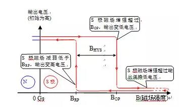
Hall Effect IC, Hall Effect Sensor IC, Hall Sensor, Hall circuit, Hall IC. Hall is sometimes translated as Hall, so it can also be called Hall IC, etc. Hereinafter referred to as Hall IC.Hall IC is usually divided into digital Hall IC and linear Hall IC according to the type of output signal. Digital Hall IC controls the output to turn on or off through the strength of external magnetic field, which acts like a switch, so it is often called switching Hall IC. The output of linear Hall IC is analog signal, and the output voltage is usually linearly related to the external magnetic field.Switch type Hall IC is often divided into four categories: single-stage Hall IC(Unipolar), latch type Hall IC(Latch), double-stage Hall IC(Bipolar) and full-stage Hall IC(Omnipolar). For the convenience of explanation, according to the general agreement, when the south pole (S pole) of the applied magnetic field approaches the marked side of Hall IC, the magnetic field direction acting on Hall IC is positive, and when the north pole (N pole) approaches the marked side, the magnetic field is negative.Single-stage Hall IC: often referred to as switch Hall IC, Hall Switch and Hall Effect Switch. Only responds to a single magnetic pole (usually S pole). As shown in Figure 1, for most unipolar Hall ICs, when the S pole faces the marking surface and the applied magnetic induction intensity B exceeds the operating point (BOP) (i.e. B>BOP>0), the output turns on and the output changes from high to low. When the magnetic induction intensity decreases below the release point (BRP) (i.e. 0<B<BRP) or is removed (B=0), the output is turned off and the output changes from low to high. If the external magnetic field of single-stage Hall IC is larger than BOP during power-on, the initial output state will be conductive. On the contrary, when the external magnetic field is smaller than the BOP during power-up, the initial output state will be off. It is an important characteristic of single-stage Hall IC that the power-on state can be determined.

1. output characteristic diagram of unipolar hall IC
Locking Hall IC: S pole and N pole must act on Hall IC alternately. As shown in Figure 2, for most latch Hall IC, when the S pole faces the marking surface and the applied magnetic induction intensity exceeds the operating point (BOP) (i.e., B>BOP>0), the output turns on and changes from high to low. When the magnetic induction intensity decreases until it is removed (B=0), the output keeps on. When the N pole faces the marking surface and the applied magnetic induction intensity exceeds the release point (BRP) (i.e., B<BRP<0), the output is turned off and the output changes from low to high. During the power-up process of Lock Hall IC, if the external magnetic field is between BOP and BRP, the initial output state will be uncertain.

Figure 2. Output characteristic diagram of latch Hall IC
Full-class Hall IC: It is a relatively new type, which treats S pole and N pole equally. Generally, as shown in fig. 3, any magnetic pole faces the marking surface, and the applied magnetic induction intensity B exceeds the operating point (BOP) (i.e. |B|>BOP), so the output turns on and changes from high to low. When the magnetic induction intensity decreases below the release point (BRP) (i.e. |B|<BRP) or is removed (B=0), the output is turned off and the output changes from low to high. There are also some full-stage Hall ICs whose output states are opposite to those above. Full-class Hall IC, which is similar to reed switch, is used in many places to replace reed switch to improve reliability.

Figure 3. Output characteristic diagram of all-pole Hall IC
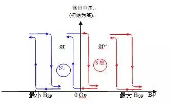
Two-stage Hall IC: It is an early type. At first, due to the limitation of semiconductor technology, the produced Hall IC has a wide sensitivity distribution range and poor consistency. The Hall of the same model, as shown in Figure 4, is partly latch type (middle curve), partly unipolar type (right curve) and partly N-pole unipolar type (right curve), which is a mixture of three kinds. Usually, the index only gives the maximum BOP(>0) and the minimum BRP(<0). Any two-stage Hall IC can't be determined as single-stage Hall IC, locking Hall IC or negative unipolar Hall IC. At present, there are few two-stage Hall IC in new models. Note that many users will mistake the two-stage Hall IC for (or call it) a locking Hall IC, and also mistake it for (or call it) an all-pole Hall IC.

Figure 4. Output characteristic diagram of bipolar Hall IC
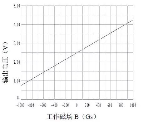
Linear Hall IC: The output is analog signal, and the output level is linearly related to the applied magnetic field in a certain range, which is called linear magnetic field range. When the applied magnetic field exceeds the linear magnetic field range, it will no longer be linear until the output is saturated, with the lowest and highest output saturation voltages.

Figure 5. Output characteristic diagram of linear Hall IC
The above are simple and commonly used Hall ICs. Besides these, some special Hall ICs with high integration and complex functions have appeared in recent years, such as differential Hall IC (double Hall IC), rotary position sensor and three-axis position sensor integrated with ADC, DAC and signal processing circuit, and brushless motor driving chip integrated with motor control and driving circuit. In addition, the current sensor IC designed by Hall principle is also a big category of Hall IC.With the popularity of mobile phones, laptops, DV and other portable devices, the power consumption of Hall IC is required, resulting in a new type of Hall IC-micro-power Hall IC. It is a kind of digital Hall IC separated separately according to its power consumption, and its internal sleep mechanism is adopted to reduce its power consumption, and its average power consumption can reach uA level. It can also be divided into three types according to functions: single-stage Hall IC, locking Hall IC and full-stage Hall IC. This kind of system is generally used for long-term battery power supply.
Disclaimer: This article is reproduced from "Test Cloud Platform". This article only represents the author's personal views, not those of Sacco Micro and the industry. It is only for reprinting and sharing, and supports the protection of intellectual property rights. Please indicate the original source and author when reprinting. If there is any infringement, please contact us to delete it.


Site Map | 萨科微 | 金航标 | Slkor | Kinghelm
RU | FR | DE | IT | ES | PT | JA | KO | AR | TR | TH | MS | VI | MG | FA | ZH-TW | HR | BG | SD| GD | SN | SM | PS | LB | KY | KU | HAW | CO | AM | UZ | TG | SU | ST | ML | KK | NY | ZU | YO | TE | TA | SO| PA| NE | MN | MI | LA | LO | KM | KN
| JW | IG | HMN | HA | EO | CEB | BS | BN | UR | HT | KA | EU | AZ | HY | YI |MK | IS | BE | CY | GA | SW | SV | AF | FA | TR | TH | MT | HU | GL | ET | NL | DA | CS | FI | EL | HI | NO | PL | RO | CA | TL | IW | LV | ID | LT | SR | SQ | SL | UK
Copyright ©2015-2025 Shenzhen Slkor Micro Semicon Co., Ltd