Service hotline
+86 0755-83044319
release time:2022-03-17Author source:SlkorBrowse:10856
Here, the basic method of converting AC (alternating current) voltage into DC (direct current) voltage, transformer mode and switching mode will be explained. In addition, the comparison between transformer mode and switching mode will be discussed.
First of all, "Why is AC/DC conversion necessary?" Let's go back to the original point first.

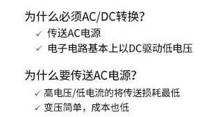
Figure 1
As we all know, the main power supply of Japanese homes or buildings is 100V or 200V AC. However, most electrical appliances are operated by electronic circuits, and almost all of them work with 5V and 3.3V DC voltages. Although there are motor equipment, incandescent bulbs, etc., which are directly driven by AC voltage, recently, relatively simple equipment such as motors and switches are almost inevitably equipped with electronic control circuits, and all electronic control circuits are driven by DC voltage. In addition, the market has gradually replaced incandescent bulbs with LEDs, but as we all know, LEDs are still basically driven by DC. That is to say, "AC is transmitted from the power transmission network, but since the electronic circuit, which is equivalent to the heart of the electronic product, is driven by DC, if the AC voltage is not converted into DC voltage, the electronic product cannot be started". The above is the answer. I believe everyone will think, "In this case, wouldn't it be nice to transmit DC power at first?" However, in fact, there are historical background factors and reasons for transmitting AC power.
You should know that Edison invented the electric lamp with incandescent bulbs in 1881. In fact, in the United States at that time, the supply of DC power was the standard. In order to promote incandescent bulbs, Edison began to put into practice the cause of DC 110V transmission to the power grid. However, when DC power is transmitted, the voltage will drop greatly, so the transmission range cannot exceed 1.5km, which leads to the power plant having to be built in the middle of the street. I can't believe it now. Nikola Tesla AC's power generation, transmission and use methods were investigated, and a current war was started with Edison. In the end, Tesla won with the AC system which can easily transform the voltage, and even if the wire is thin and long, it will not cause too much loss when transmitting power, and the result has continued until now.
Advantages of AC
It can keep high voltage/low current during power transmission, and reduce voltage drop (I2R loss).
A DC drive device that can easily convert AC power into DC power and easily supply electric power.
In fact, after the power plant sends out thousands to 20,000 V AC high voltage, it will be reduced to 100V and 200V through the transformer on the utility pole before being transmitted to the general households.
This is a digression. At present, the socket in the house supplies AC power, so each device must install its own AC/DC conversion circuit. For this part, from the point of view of energy saving and miniaturization, it has to be said that it is superfluous. Recently, in the smart home concept tested and studied in various places, the system of directly supplying DC power from the socket in the house has also been considered. Even so, it doesn't mean that the power transmission facilities can be rapidly converted into DC, or AC/DC conversion is unnecessary. In this system, household power supply devices that supply DC power still have to be equipped with high-power AC/DC converters with high power and efficiency, and medium-power AC/DC converters installed nearby.
Then, let's talk about another basic knowledge. In the foregoing, it is mentioned that "it can be easily converted from AC to DC", but it belongs to the function of "rectification", which is the foundation of AC/DC conversion, so it is necessary to know its architecture first.

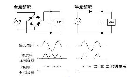
Figure 2
Figure 2 shows full-wave rectification, which belongs to the basic type of rectification, and the role of half-wave rectification. Either way, the input AC voltage is connected to the diode to capture the amplitude of the negative wave. Half-wave rectification only uses one diode to catch the amplitude of the negative wave, so the negative wave disappears, leaving only half the waveform, so it is called half wave. Full-wave rectification uses a bridge diode composed of four diodes, which can rotate the negative wave and make it appear in the positive wave region, while the full waveform can be displayed by DC.
After DC conversion, the capacitor is used to smooth the waveform. However, even if the waveform is smooth, there will still be Ripple (ripple), and its amplitude ripple voltage will change due to the capacitance and load of the capacitor. When the capacitance of the capacitor is the same as the load, the ripple voltage of full-wave rectification will be smaller than that of half-wave rectification.
Disclaimer: This article is reproduced from "Notes of Electronic Engineers". This article only represents the author's personal views, and does not represent the views of Sacco Micro and the industry. It is only for reprinting and sharing to support the protection of intellectual property rights. Please indicate the original source and author when reprinting. If there is any infringement, please contact us to delete it.
Company Tel: +86-0755-83044319
Fax/fax:+86-0755-83975897
Email: 1615456225@qq.com
QQ: 3518641314 Manager Li
QQ: 332496225 Manager Qiu
Address: Room 809, Block C, Zhantao Technology Building, No.1079 Minzhi Avenue, Longhua New District, Shenzhen


Site Map | 萨科微 | 金航标 | Slkor | Kinghelm
RU | FR | DE | IT | ES | PT | JA | KO | AR | TR | TH | MS | VI | MG | FA | ZH-TW | HR | BG | SD| GD | SN | SM | PS | LB | KY | KU | HAW | CO | AM | UZ | TG | SU | ST | ML | KK | NY | ZU | YO | TE | TA | SO| PA| NE | MN | MI | LA | LO | KM | KN
| JW | IG | HMN | HA | EO | CEB | BS | BN | UR | HT | KA | EU | AZ | HY | YI |MK | IS | BE | CY | GA | SW | SV | AF | FA | TR | TH | MT | HU | GL | ET | NL | DA | CS | FI | EL | HI | NO | PL | RO | CA | TL | IW | LV | ID | LT | SR | SQ | SL | UK
Copyright ©2015-2025 Shenzhen Slkor Micro Semicon Co., Ltd