Service hotline
+86 0755-83044319
release time:2024-06-06Author source:SlkorBrowse:11430
In the field of electronics engineering, the Zener diode is an indispensable electronic component that provides stable voltage output in circuits, ensuring overall circuit stability and reliability. This article will provide a detailed overview of the performance characteristics and applications of the ZM4742A Zener diode.

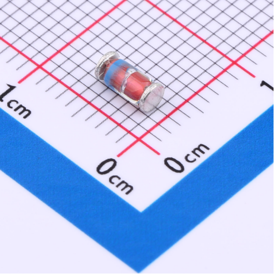
Slkor Voltage Regulator Diode ZM4742A product photo
I. Overview of the ZM4742A Zener Diode
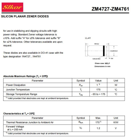
The ZM4742A is a high-performance Zener diode with a nominal voltage of 12V, offering a precision of up to ±5% and a power rating of 1W. This Zener diode features low reverse current and low impedance, enabling it to deliver stable voltage output in various circuits, ensuring stable circuit operation.

Slkor Voltage Regulator Diode ZM4742A specification
II. Performance Characteristics of the ZM4742A Zener Diode
High Precision Regulation: The ZM4742A Zener diode boasts a regulation precision of ±5%, maintaining stable output voltage within a wide range of power supply voltage fluctuations. This characteristic makes the ZM4742A widely applicable in circuits requiring high-precision voltage regulation.
High Power Handling Capacity: With a power rating of 1W, the ZM4742A Zener diode can withstand high currents and voltages, meeting the demands of high-power circuits.
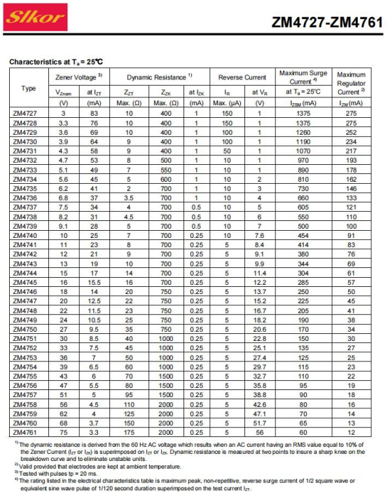
Low Reverse Current: Prior to reaching the breakdown voltage, the reverse current of the ZM4742A Zener diode is only 5μA@9.1V, aiding in reducing circuit power consumption and enhancing circuit efficiency.
Low Impedance: The impedance of the ZM4742A Zener diode is 9Ω, indicating it possesses low dynamic impedance, allowing for rapid response to current changes and maintaining stable output voltage.

Parameters of Slkor Voltage Regulator Diode ZM4742A
III.Usage Notes
When using the ZM4742A voltage regulator diode, make sure that the input voltage does not exceed its rated power and rated voltage range.
When designing circuits, take into consideration the temperature coefficient and power consumption characteristics of the voltage regulator diode to ensure the stability and reliability of the circuit under different temperature and load conditions.
During soldering and installation, be careful to avoid causing mechanical or thermal damage to the voltage regulator diode.
Before use, inspect the appearance and pins of the voltage regulator diode to ensure there is no damage or short circuit.
IV.Application Circuit Simulation Experiment of Voltage Regulator Diode
Experiment Purpose
This experiment aims to simulate the application of the voltage regulator diode in a circuit using simulation software, verify its voltage regulation performance, and understand the role of the current-limiting resistor in the circuit.
Principle of the Experiment
A voltage regulator diode is a special type of diode that can maintain a nearly constant voltage across its terminals in the reverse breakdown state. This characteristic makes the voltage regulator diode widely used in circuits that require a stable output voltage. In the application circuit of the voltage regulator diode, a current-limiting resistor is usually connected in series to limit the current flowing through the voltage regulator diode and protect its normal operation.
Experimental Procedure
Prepare simulation software:
● Choose a suitable circuit simulation software such as Multisim or LTspice.
Build the circuit:
● In the simulation software, select the voltage regulator diode ZM4742A (regulated value 12V, accuracy ±5%, power 1W, reverse current 5μA@9.1V, impedance 9Ω) and an appropriate current-limiting resistor.
● Construct a basic voltage regulation circuit by connecting the voltage regulator diode between the power supply and the load, with the current-limiting resistor in series before the voltage regulator diode.
Set parameters:
● Set the power supply voltage slightly above the regulated value of the voltage regulator diode, for example, 10V.
● Configure the resistance value of the load resistor as needed.
● Adjust the resistance value of the current-limiting resistor and observe its impact on the output voltage.
● Run the simulation: Start the simulation program and observe the waveform and stability of the output voltage.
Data analysis:
● Record the output voltage values at different resistance values of the current-limiting resistor.
● Analyze the effect of the current-limiting resistor on the output voltage.
Experimental Results and Discussion
● Stability of the output voltage:
With the appropriate resistance value of the current-limiting resistor, the voltage regulator diode can effectively stabilize the output voltage near the nominal value (in this case, 12V ±5%).
When the resistance value of the current-limiting resistor is too small, the current flowing through the voltage regulator diode may be too large, leading to overheating or damage to the diode and causing unstable output voltage.
When the resistance value of the current-limiting resistor is too large, the voltage regulator diode may not be able to provide enough current to maintain a constant output voltage, which also affects the output voltage.
● Role of the current-limiting resistor:
The current-limiting resistor restricts the current in the circuit, protecting the voltage regulator diode from damage due to excessive current.
By adjusting the resistance value of the current-limiting resistor, the output voltage can be indirectly adjusted to meet the requirements of different circuits.
Experimental Conclusion
Through this simulation experiment, we have verified the voltage regulation performance of the voltage regulator diode in the circuit and understood the role of the current-limiting resistor. The experimental results indicate that with the appropriate resistance value of the current-limiting resistor, the voltage regulator diode can effectively stabilize the output voltage near the nominal value, providing a stable voltage output for the circuit. Additionally, the current-limiting resistor plays a crucial role in limiting current and protecting the voltage regulator diode, which is essential for ensuring the stability and reliability of the circuit.
About Slkor:
Slkor has research and development offices in Busan, South Korea, Beijing, China, and Suzhou, China. Most of the wafer manufacturing and packaging and testing are carried out within China. The company employs and collaborates with individuals and organizations worldwide, with a laboratory for product performance and reliability testing and a central warehouse located at its headquarters in Shenzhen. Slkor has filed for over a hundred invention patents, offers more than 2,000 product models, and serves over ten thousand customers globally. Its products are exported to countries and regions including Europe, the Americas, Southeast Asia, and the Middle East, making it one of the rapidly growing semiconductor companies in recent years. With well-established management systems and streamlined workflows, Slkor has rapidly enhanced the brand awareness and reputation of its "SLKOR" brand through its outstanding quality and standardized services. Its product range includes three major series: diodes, transistors, and power devices, with recent introductions of new products such as Hall elements and analog devices, expanding its presence in sensors, Risc-v microcontrollers, and other product categories.


Site Map | 萨科微 | 金航标 | Slkor | Kinghelm
RU | FR | DE | IT | ES | PT | JA | KO | AR | TR | TH | MS | VI | MG | FA | ZH-TW | HR | BG | SD| GD | SN | SM | PS | LB | KY | KU | HAW | CO | AM | UZ | TG | SU | ST | ML | KK | NY | ZU | YO | TE | TA | SO| PA| NE | MN | MI | LA | LO | KM | KN
| JW | IG | HMN | HA | EO | CEB | BS | BN | UR | HT | KA | EU | AZ | HY | YI |MK | IS | BE | CY | GA | SW | SV | AF | FA | TR | TH | MT | HU | GL | ET | NL | DA | CS | FI | EL | HI | NO | PL | RO | CA | TL | IW | LV | ID | LT | SR | SQ | SL | UK
Copyright ©2015-2025 Shenzhen Slkor Micro Semicon Co., Ltd