Service hotline
+86 0755-83044319

release time:2022-03-17Author source:SlkorBrowse:11018
The following points should be paid attention to in the selection of domestic IGBT modules:
Loss of IGBT module
The loss of IGBT module comes from the loss of internal IGBT and diode (freewheeling FWD, rectification) chips, mainly the loss caused by IGBT and FWD.
IGBT is not an ideal switch, which is embodied in:
1) Saturated voltage when IGBT is turned on–vcesat
2) IGBT has switching energy consumption when switching–-Eon and Eoff, which is the root of IGBT loss. Vcesat causes conduction loss, while Eon and Eoff cause switching loss. Turn-on loss+switching loss = total IGBT loss.
FWD also has two losses, because:
(1) When conducting in the forward direction (i.e. freewheeling), there is a forward conducting voltage: Vf
(2) There is reverse recovery energy consumption in the process of reverse recovery: Erec. Vf leads to conduction loss, and Erec leads to switching loss. On-loss+switching loss = FWD total loss.
The Vcesat, Eon, Eoff, Vf and Erec embody the technical characteristics of IGBT/FWD chips. Therefore, IGBT/FWD chip technology is different, so are Vcesat, Eoff, Vf and Erec.
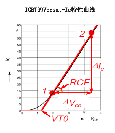
Loss of IGBT module -IGBT conduction loss
The relationship between Vcesat and Ic can be described by the approximate linear method in the left figure.
Means: Vcesat = Vt0+Rce× Ic
Turn-on loss of IGBT:
Pcond = d * Vcesat × Ic, where D is the on duty ratio of IGBTThe magnitude of IGBT saturation voltage is related to the passing current (Ic),The junction temperature (Tj) of the chip is related to the gate voltage (Vge).
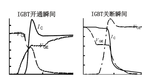
Loss of IGBT module -IGBT switching loss
The reason why IGBT has switching power consumption is that the current and voltage have overlapping periods at the moment of turning on and off.
When Vce is close to the test conditions, Eon and Eoff can be approximately regarded as proportional to Ic and Vce:
Eon = EON × Ic/IC,NOM ×
Vce/ test conditionsEoff = EOFF×
Ic/IC,NOM×
Vce/ test conditions
Switching loss of IGBT: Psw = fsw × (Eon+Eoff), fsw is the switching frequency.
The power consumption of IGBT is related to the current (Ic), voltage (Vce) and junction temperature (Tj) of the chip.
Eon definition: 10% Ic to 2%Vce n
Eoff definition: 10% Vce to 2%Ic
Loss of IGBT module -FWD conduction loss
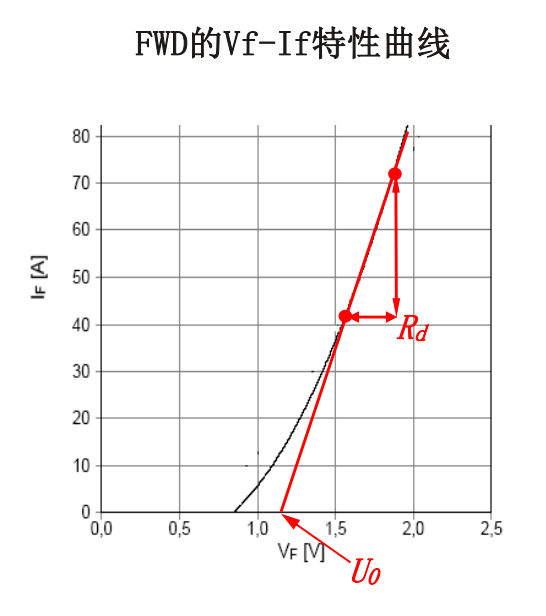
The relationship between Vf and If can be expressed by the approximate linear method in the left figure:
Vf = U0 + Rd × If
Turn-on loss of FWD: Pf = d * Vf × If, where d is the on duty cycle of FWD.
The module gives the characteristic value of FWD's forward conduction voltage: VF, and the test conditions.
The FWD forward conduction voltage is related to the current (If) and the junction temperature (Tj) of the chip.
Loss of IGBT module -FWD switching loss
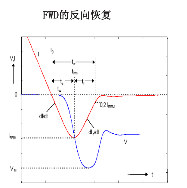
Reversal is the inherent characteristic of FWD, which occurs at the moment when the forward conduction turns to the reverse blocking, and then returns to the reverse blocking state after passing the reverse current.
When Vr is close to the test conditions, Erec can be approximately regarded as proportional to If and Vr:Erec = EREC ×
If/IF,NOM × Vr/ test conditions
Switching loss of FWD: Prec = fsw× Erec and fsw are switching frequencies.
The energy consumption of FWD reverse recovery is related to the current (If), current change rate dif/dt, reverse voltage (Vr) and junction temperature (Tj) of the chip during forward conduction.
Loss of IGBT module-summary
Conduction loss:
(1) related to IGBT chip technology
(2) It is related to the operating conditions: it is proportional to the current and the duty cycle of IGBT, and increases with the increase of Tj.
(3) It is related to driving conditions: it decreases with the increase of Vge.
switching loss:
(1) related to IGBT chip technology
(2) Related to working conditions: proportional to switching frequency, current and voltage, increasing with Tj.
(3) It is related to driving conditions: it increases with the increase of Rg and decreases with the increase of gate turn-off voltage.
FWD
Conduction loss:
(1) related to FWD chip technology
(2) Related to working conditions: proportional to current and FWD duty cycle.
switching loss:
(1) related to FWD chip technology
(2) Related to working conditions: proportional to switching frequency, current and voltage, increasing with Tj.
Temperature of IGBT module
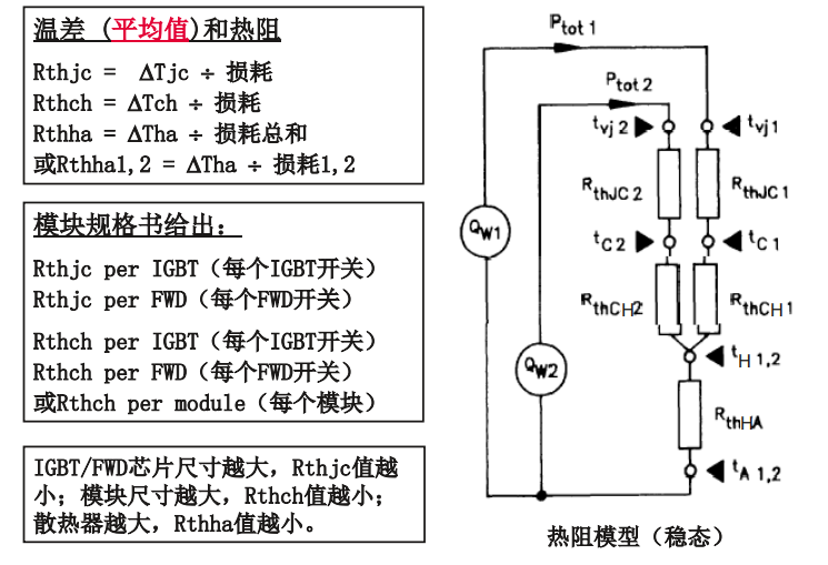
MacArthur Wei Yang: RTCH of arm = ×n of modules Rth = rth _ IGBT//rth _ FWD of each arm MacArthur Wei Yang: RTHA of arm = RTHA & Times: n Yune, poor guy Zhou Yafu? Zhou Yafu? Zhou Yafu (IGBT+FWD), n Wu Yaling Wu Yaling Wu Yaling-Hello.
For PIM with rectifier bridge, the conversion of Rthch can be calculated according to the ratio between Rthjc.
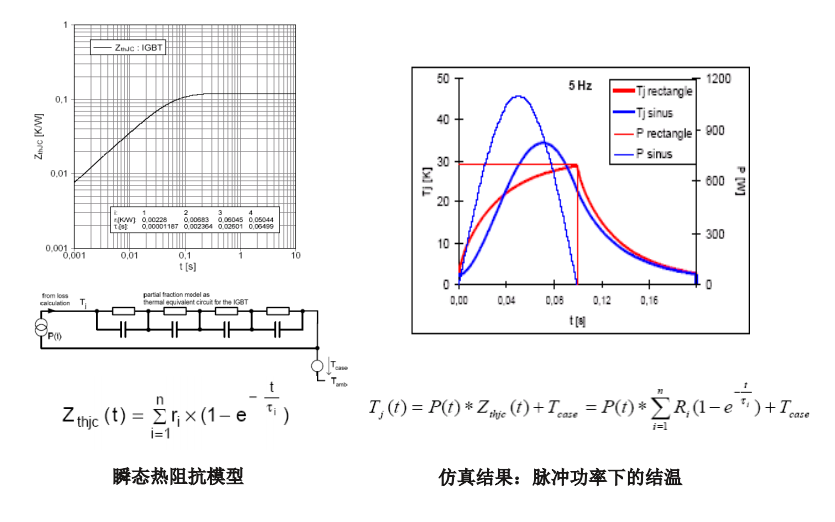
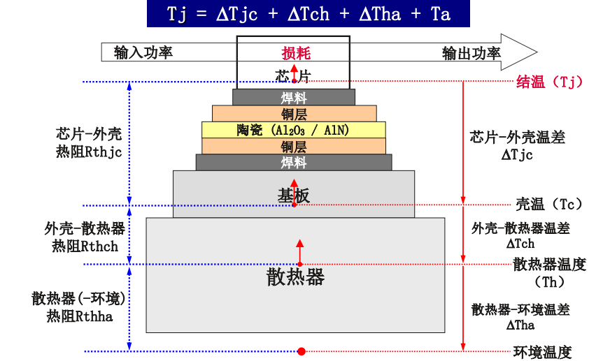
Temperature of IGBT module-summary
The temperature difference T of each part of IGBT module depends on
(1) Loss (chip technology, operating conditions, driving conditions);
(2) Thermal resistance (module specification and size)
The junction temperature of the chip is the sum of the temperature difference of each part and the ambient temperature: Tj = ΔTjc +ΔTch +ΔTha+Ta.If the shell temperature Tc is constant, Tj = ΔTjc+Tc;
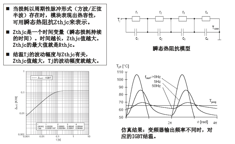
If the radiator temperature Th is constant, Tj =ΔTjh+Th.Average junction temperature of IGBT depends on average loss, Rthjc and shell temperature Tc.In actual operation, the junction temperature of IGBT fluctuates, and its fluctuation depends on the transient loss and Zthjc, which is related to the operating conditions (such as the output frequency of inverter).The peak junction temperature of IGBT is the average junction temperature+fluctuation amplitude.
Conclusion:
The junction temperature (average/peak value) of IGBT is related to chip technology, operating conditions, driving conditions, IGBT specifications, module size, heat sink size and ambient temperature.
Safe operation of IGBT module
Basic conditions for safe operation:
Temperature: peak value TJ _ peak of IGBT junction temperature ≤ 125c & deg; (150C° *)
The module specification gives the maximum allowable junction temperature of two IGBT:Tjmax = 150C° (150C° *)-refers to the constant conduction state without switch operation;
Tvj(max) = 125° (150C° *)-refers to the normal switch operation state.
Tvj(max) specifies the maximum junction temperature allowed by IGBT's turn-off current, short circuit and power alternation (PC).* 600V IGBT3; 200v and 1700V IGBT4;; 3300V IGBT3 nShort circuit time: Vcc=2500V, Vge<=15V, Tvj=150° ,
Tp<=10usOthers: Vce ≤ VCES (i.e. voltage specification of IGBT)Vge ≤VGES(± 20V) Ic is specified by RBSOA. Under the working condition of continuous switching, it shall not exceed 2× IC,NOM。 Minimum opening time, etc.
Sawei semiconductor SLKOR
Shenzhen Sacco Micro slkor Semiconductor Co., Ltd. is a high-tech enterprise engaged in IC design, production and sales. Safeway's "SLKOR" brand and technology originated from South Korea. After several years' unremitting efforts by Mr. Song Shiqiang, the general manager, and Sakewei's team, it has already realized the localization of key links such as IP design, wafer flow, packaging and testing, sales service, etc. of component products, and has become an out-and-out "China Core", striving to break through the "bottleneck" situation of our chips in Europe and America. Our main products are MOS FET, hall Hall element, IGBT single transistor, SiC silicon carbide device, high-speed optocoupler, ESD static protection diode, TVS transient suppression diode, Schottky diode, COOLMOS, power management IC, etc. Since 2010, SAKO Micro has developed and produced the third generation semiconductor silicon carbide SiC components. Its applications include new energy vehicles, new energy power generation, high-power switching power supply and UPS uninterruptible power supply, etc. It also has some applications in aerospace. "SLKOR" brand common power device MOS tube and other products are widely used in lithium battery protection board, sweeping robot, TWS Bluetooth headset, electronic cigarette, outdoor lighting, PCBA board factory and other industries.
Site Map | 萨科微 | 金航标 | Slkor | Kinghelm
RU | FR | DE | IT | ES | PT | JA | KO | AR | TR | TH | MS | VI | MG | FA | ZH-TW | HR | BG | SD| GD | SN | SM | PS | LB | KY | KU | HAW | CO | AM | UZ | TG | SU | ST | ML | KK | NY | ZU | YO | TE | TA | SO| PA| NE | MN | MI | LA | LO | KM | KN
| JW | IG | HMN | HA | EO | CEB | BS | BN | UR | HT | KA | EU | AZ | HY | YI |MK | IS | BE | CY | GA | SW | SV | AF | FA | TR | TH | MT | HU | GL | ET | NL | DA | CS | FI | EL | HI | NO | PL | RO | CA | TL | IW | LV | ID | LT | SR | SQ | SL | UK
Copyright ©2015-2025 Shenzhen Slkor Micro Semicon Co., Ltd
