What is topology? The so-called circuit topology is the connection method of power devices and electromagnetic components in the circuit, and the design of magnetic components, closed-loop compensation circuit and all other circuit components depend on the topology. The most basic topologies are buck, boost and boost/buck, isolated flyback, forward, push-pull, half-bridge and full-bridge converters.
There are about 14 common topologies of switching power supply, each of which has its own characteristics and applicable occasions. The selection principle is to see whether it is high power or low power, high voltage or low voltage output, and whether there are as few components as possible.
Therefore, it is very important to be familiar with the advantages, disadvantages and application fields of different topologies in order to properly select topologies. The wrong choice will make the diet design doomed to failure from the beginning. The following summarizes 20 basic switching power supply topologies to help the system master the working principle and basic characteristics of each circuit structure.
Comparison of 20 Switching Power Supply Topologies
Common basic topology of:
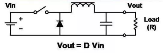
■ Buck step-down
■ Boost boost
■ Buck-Boost buck-boost
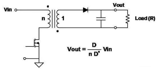
■ Flyback flyback
■ Forward forward excitation
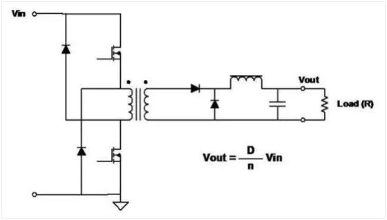
■ Two-Transistor Forward double transistor forward
■ Push-Pull push-pull
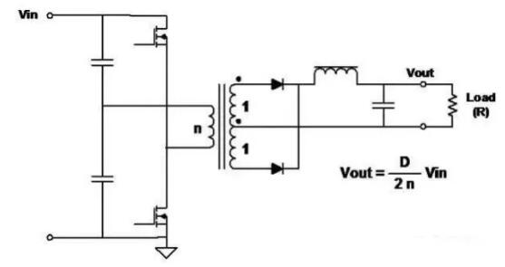
■ Half Bridge Half Bridge
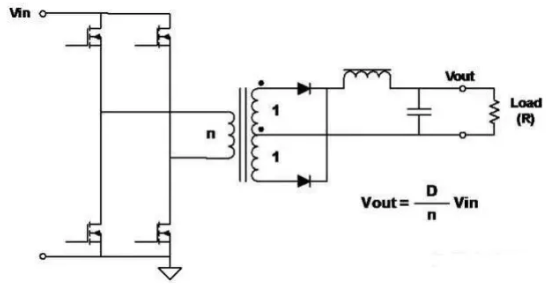
■ Full Bridge Full Bridge
■ SEPIC
■ C’uk
Basic pulse width modulation waveform of
These topologies are all related to switching circuits, and the basic pulse width modulation waveform is defined as follows:
Features:
■ Reduce the input to a lower voltage.
■ Probably the simplest circuit.
■ The inductor/capacitor filter smoothes the square wave after switching.
■ Output is always less than or equal to input.
■ Discontinuous input current (chopping)
■ Smooth output current
Features:
■ Raise the input to a higher voltage.
■ Same as step-down, but the inductor, switch and diode are rearranged.
■ The output ratio is always greater than or equal to the input (ignoring the forward voltage drop of the diode)
■ Input current smoothing
■ Discontinuous output current (chopping)
Features:
■ Another arrangement method of inductors, switches and diodes
■ Combines the disadvantages of buck and boost circuits.
■ Discontinuous input current (chopping)
■ The output current is also discontinuous (chopping)
■ The output is always opposite to the input (note the polarity of the capacitor), but the amplitude can be smaller or larger than the input.
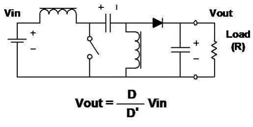
■ "Flyback" converter is actually in the form of buck-boost circuit isolation (transformer coupling).
Features:
■ Works like a buck-boost circuit, but the inductor has two windings, which serve as both a transformer and an inductor.
■ The output can be positive or negative, determined by the polarity of the coil and diode.
■ The output voltage can be larger or smaller than the input voltage, which is determined by the turns ratio of the transformer.
■ This is the simplest isolated topology.
■ Multiple outputs can be obtained by adding secondary windings and circuits.
Features:
■ Transformer coupling form of step-down circuit.
■ Discontinuous input current and smooth output current.
■ Because the transformer is used, the output can be larger or smaller than the input, and it can be of any polarity.
■ Multiple outputs can be obtained by adding secondary windings and circuits.
■ The transformer core must be demagnetized in each switching cycle. The common practice is to add a winding with the same number of turns as the primary winding.
■ The energy stored in the primary inductor during the switch-on phase is released through additional windings and diodes during the switch-off phase.
Features:■ Transformer coupling form of step-down circuit.■ Discontinuous input current and smooth output current.■ Because the transformer is used, the output can be larger or smaller than the input, and it can be of any polarity.■ Multiple outputs can be obtained by adding secondary windings and circuits.■ The transformer core must be demagnetized in each switching cycle. The common practice is to add a winding with the same number of turns as the primary winding.■ The energy stored in the primary inductor during the switch-on phase is released through additional windings and diodes during the switch-off phase.
Features:
■ Two switches work at the same time.
■ When the switch is off, the energy stored in the transformer reverses the polarity of the primary and turns on the diode.Main advantages:
■ The voltage on each switch will never exceed the input voltage.
■ There is no need to reset the winding track.
Features:
■ Switch (FET) drives different phases and performs pulse width modulation (PWM) to adjust the output voltage.
■ Good utilization ratio of transformer core-power transmission in both half cycles.
■ Full-wave topology, so the output ripple frequency is twice that of the transformer.
■ The voltage applied to the FET is twice the input voltage.
Features:
■ Topology structure of higher power converter is very commonly used.
■ Switch (FET) drives different phases and performs pulse width modulation (PWM) to adjust the output voltage.
■ Good utilization ratio of transformer core-power transmission in both half cycles. And the utilization ratio of primary winding is better than that of push-pull circuit.
■ Full-wave topology, so the output ripple frequency is twice that of the transformer.
■ The voltage applied to the FET is equal to the input voltage.
Features:
■ The most commonly used topology of higher power converters.
■ Switches (FETs) are driven in the form of diagonal pairs, and pulse width modulation (PWM) is performed to regulate the output voltage.
■ Good utilization ratio of transformer core-power transmission in both half cycles.
■ Full-wave topology, so the output ripple frequency is twice that of the transformer.
■ The voltage applied to FETs is equal to the input voltage.
■ At a given power, the primary current is half of the half bridge.
SEPIC single-ended primary inductor converter
Features:
■ The output voltage can be greater or less than the input voltage.
■ Like the boost circuit, the input current is smooth, but the output current is discontinuous.
■ Energy is transferred from the input to the output through a capacitor.
■ Two inductors are required.
C 'uk (patent of Slobodan C 'uk)
Features:
■ Output inversion
■ The amplitude of the output voltage can be larger or smaller than that of the input.
■ Both the input current and the output current are smooth.
■ Energy is transferred from the input to the output through a capacitor.
■ Two inductors are required.
■ Inductors can be coupled to obtain zero ripple inductor current.
Details of the circuit work
Explain the working details of the following topologies:
■ Step-down regulator: continuous conduction, critical conduction and discontinuous conduction.
■ Boost regulator (continuous conduction)
■ Transformer operation
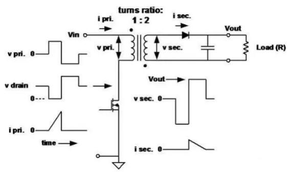
■ Flyback transformer
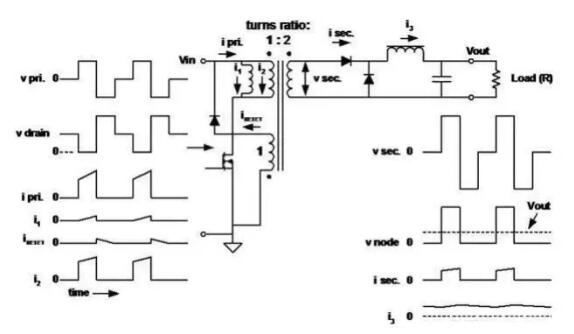
■ Forward transformer
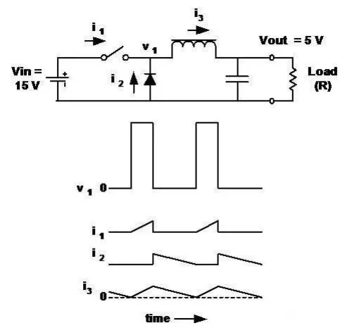
Buck- buck regulator-continuous conduction
Features:
■ Inductor current is continuous.
■ Vout is the average value of its input voltage (V1).
■ The output voltage is the input voltage multiplied by the load ratio (D) of the switch.
■ When switched on, the inductor current flows out of the battery.
■ Current flows through the diode when the switch is off.
■ Ignore the losses in switches and inductors, and D has nothing to do with the load current.
■ The buck regulator and its derivative circuits are characterized by:The input current is discontinuous (chopping) and the output current is continuous (smoothing).
Buck- buck regulator-critical conduction
■ The inductor current is still continuous, but only "reaches" zero when the switch is turned on again, which is called "critical conduction". The output voltage is still equal to the input voltage multiplied by d.
Buck- buck regulator-discontinuous conduction
■ In this case, the current in the inductor is zero for a period of time in each cycle.
■ The output voltage is still (always) the average value of v1.
■ The output voltage is not the input voltage multiplied by the load ratio (D) of the switch.
■ When the load current is lower than the critical value, D changes with the load current (while Vout remains the same).
■ The output voltage is always greater than (or equal to) the input voltage.
■ Continuous input current and discontinuous output current (opposite to buck regulator).
■ The relationship between output voltage and load ratio (D) is not as simple as in buck regulators. In the case of continuous conduction:
In this example, Vin = 5,Vout = 15, and D = 2/3. Vout = 15, D = 2/3.
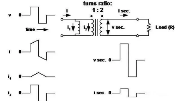
Operation of transformer (including the function of primary inductor)
■ Transformer is regarded as an ideal transformer, and its primary (magnetization) inductance is connected in parallel with the primary.
■Here, the primary inductance is very low, which is used to determine the peak current and stored energy. When the primary switch is turned off, energy is transferred to the secondary.
Forward forward forward converter transformer
■ The primary inductance is high because there is no need to store energy.
■ The magnetizing current (i1) flows into the "magnetizing inductor" to demagnetize the magnetic core (reverse voltage) after the primary switch is turned off.
■ Here, the most common circuit topology in switching power conversion is reviewed.
■ There are many other topologies, but most of them are combinations or variations of the topologies described here.
■ Each topology contains unique design tradeoffs:1) the voltage applied to the switch2) Chopping and smoothing the input and output current3) Utilization ratio of winding
■ Choosing the best topology requires research:1) input and output voltage range2) Current range3) The ratio of cost to performance, size to weight
Disclaimer: This article is reproduced from "Power System Design". This article only represents the author's personal views, and does not represent the views of Sacco Micro and the industry. It is only for reprinting and sharing to support the protection of intellectual property rights. Please indicate the original source and author when reprinting. If there is any infringement, please contact us to delete it.