Service hotline
+86 0755-83044319
release time:2022-03-17Author source:SlkorBrowse:11015
IGBT, fully called insulated gate bipolar transistor, is a semiconductor device widely used in power electronics industry. The module described here is a specific packaging form, which is the carrier of IGBT chip and plays a protective role.
In recent years, with the vigorous development of new energy automobile industry, more and more automotive IGBT products have emerged. Knowing the semiconductor standards of automobile industry can deepen the understanding of device characteristics and help developers choose suitable products.
Semiconductor standard
Within the semiconductor standard system, there are JEDEC (Joint Electron Device Engineering Council), IEC (International Electrotechnical Commission) and other standards.
Automobile industry standard
In the automotive industry, there is AEC (Automotive Electronics Council) standard, and AQG324, the reliability test specification for IGBT modules on vehicles, was published by ECPE (European Center for Power Electronics), named LV324 in the early stage, and compiled by automobile manufacturers Volkswagen, Audi, BMW, Porsche and Daimler.
QC/T 1136 Automotive IGBT Standard
Led by CATARC in China, China FAW wrote QC/T 1136-2020 Environmental Test Requirements and Test Methods for Insulated Gate Bipolar Transistor Modules for Electric Vehicles, which was first published on April 1, 2021. It is the first domestic standard for IGBT modules for vehicles, and is used to standardize the reliability test items and requirements of semiconductor suppliers in IGBT modules. As a member of the drafting group, Infineon participated in the formulation of the standard.
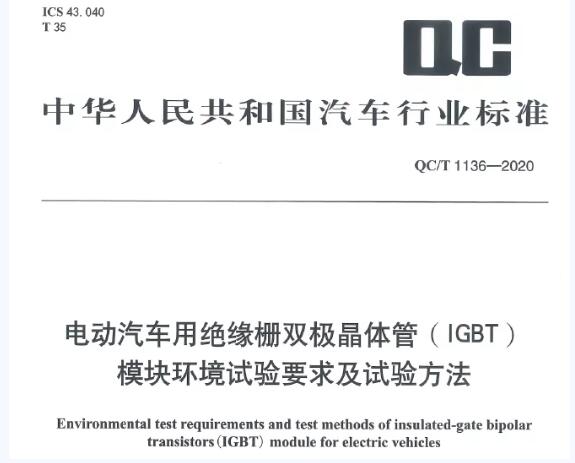
QC/T 1136-2020 specifies the requirements and test methods of environmental adaptability of IGBT modules for electric vehicles. The full text is divided into eight parts, which are preface, scope, normative citation documents, terms and definitions, symbols and abbreviations, environmental adaptability requirements, test methods and appendix. The fifth chapter is the requirements of environmental adaptability (see Table 1), and the sixth chapter is the test method. Unless otherwise specified, all tests shall be carried out under the following environmental conditions:
-Environment:+18℃ ~+28℃;
-Relative humidity: 45% ~ 75%;
-Atmospheric pressure: 86 kPa ~ 106 kPa;
-Altitude: no more than 1000 meters. If it exceeds 1000m, it shall be corrected according to the relevant provisions of GB/T18488.1-2015.
Table 1. QC/T 1136 Environmental Test Requirements and Reference Marking of Automotive IGBT Module
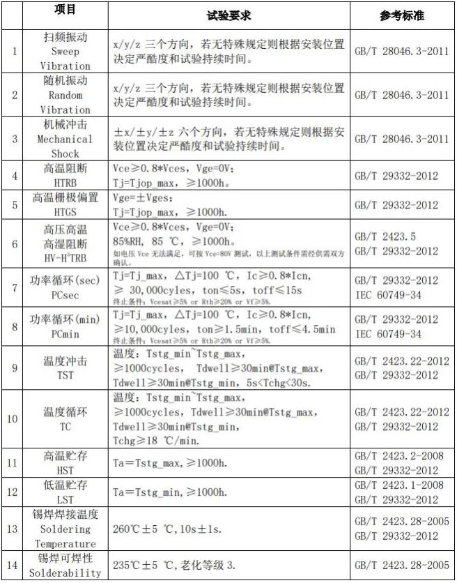
In Table 1, the test items can be classified into two categories: chip reliability and package reliability, among which:
01
Chip reliability
Test items related to chip reliability include high-temperature blocking test, high-temperature grid bias test, high-voltage high-temperature high-humidity blocking test and power cycle (second level) test.
Table 2. Requirements for chip reliability test
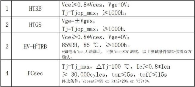
Considering that automobile parts are often exposed to harsh weather conditions, it is necessary to ensure that automobile products are protected from corrosion or oxidation under high temperature, high humidity and high pressure. Among them, the high-temperature and high-humidity blocking test is based on the voltage of 80V required by AEC-Q101, but considering that the bus voltage is much higher than 80V in actual operating conditions, HV-H³ is designed; TRB test. In order to pass the high temperature and high humidity blocking test, special attention should be paid to the design of passivation layer in chip design.

Figure 2. Test results before and after optimizing passivation layer
PCsec test is to simulate the change of bonding wire and chip junction temperature caused by load change in practical application, and the test result is the life (cycle number) under specific temperature rise condition. During the test, a second load current was applied to the IGBT module, and the temperature of the cooling system was adjusted to make the junction temperature reach the maximum allowable working temperature. In this process, we mainly test the reliability of the connection point between the bonding wire and the chip and the bonding layer between IGBT chip and DCB. The test termination condition is that the conduction voltage drop exceeds 5% of the initial value or the system thermal resistance exceeds 20% of the initial value.
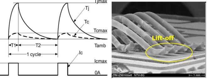
Figure 3. PC(sec) Testing and Failure Phenomenon
02
Packaging reliability
Test items related to package reliability include mechanical vibration/shock, power cycle (PCsec/PCmin), temperature shock, temperature cycle (passive), high/low temperature storage, soldering temperature and solderability test.
Table 3. Package reliability test requirements
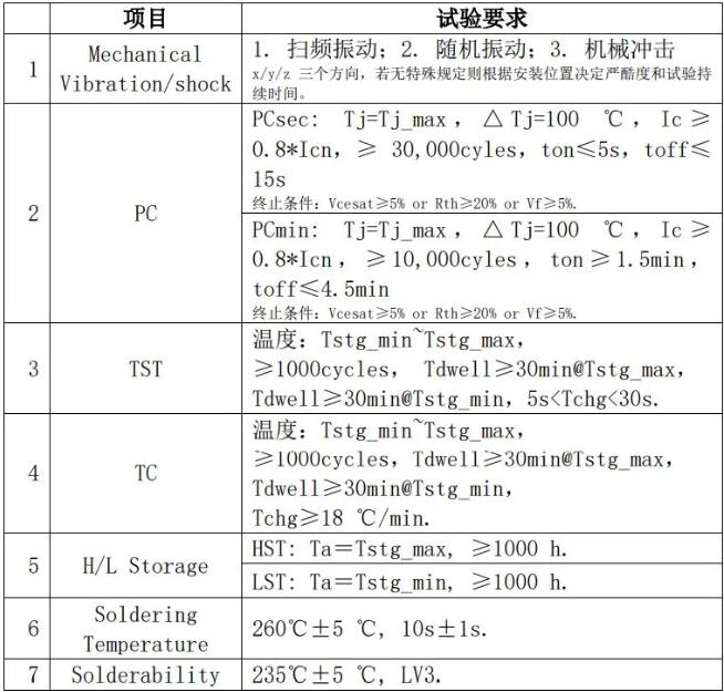
In terms of mechanical vibration, considering the difference of the requirements of the installation position on the vibration level (severity), no specific limit is given here, and the vibration level should be selected according to the installation position on the vehicle body (refer to GB/T 28046.3-2011). Mechanical vibration test will lead to the cracking of the binding wire itself, the loosening of the binding wire and other related connectors, and the cracking of the packaging shell, etc. Therefore, IGBT modules must meet the relevant severity level.
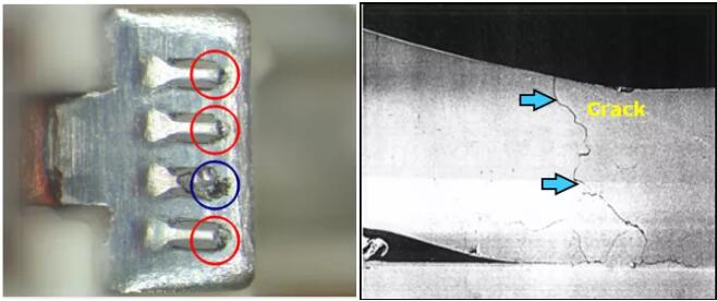
Figure 4. Failure of binding wire caused by mechanical vibration
The main difference between power cycle test (PCsec/PCmin) and temperature cycle/shock test is the heat source. The power cycle heats the chip through the load current, while the temperature cycle/shock heats the whole package by the external heat source.
Power cycle (PCmin): check the reliability of the connection point between the bonding wire and the chip, the reliability of the bonding layer between the chip and DCB, and the reliability of the bonding layer between DCB and Baseplate.
Temperature cycle (TC): slowly heat the whole package from the bottom of the Baseplate to check the reliability of the connection between materials with different thermal expansion coefficients.
Temperature shock (TST): quickly (< 30s) place the IGBT module from a high temperature (low temperature) environment to a low temperature (high temperature) environment, and check the adaptability of the module under the scene of rapid temperature alternation.
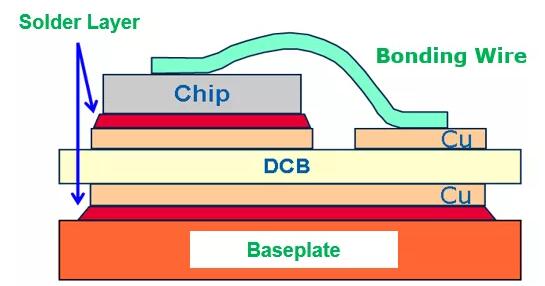
Figure 5. Layering diagram of IGBT module
High-low temperature storage test is to consider the minimum storage time of IGBT module in a specific temperature environment. The welding temperature and solderability are proposed for the signal Pin on IGBT module, and the signal Pin for crimping should also meet the solderability requirements.
Finally, QC/T 1136-2020 is a recommended standard for environmental reliability test of automotive IGBT modules, which includes test items and requirements related to chip reliability and package reliability in modules. Yingling has accumulated many years of practical experience in the power semiconductor industry, and is committed to providing our customers with high-reliability automotive products.
Disclaimer: This article is reproduced from "Infineon Automotive Electronics Ecosphere". This article only represents the author's personal views, and does not represent the views of Sacco Micro and the industry. It is only for reprinting and sharing to support the protection of intellectual property rights. Please indicate the original source and author when reprinting. If there is any infringement, please contact us to delete it.
Company Tel: +86-0755-83044319
Fax/fax:+86-0755-83975897
Email: 1615456225@qq.com
QQ: 3518641314 Manager Li
QQ: 332496225 Manager Qiu
Address: Room 809, Block C, Zhantao Technology Building, No.1079 Minzhi Avenue, Longhua New District, Shenzhen


Site Map | 萨科微 | 金航标 | Slkor | Kinghelm
RU | FR | DE | IT | ES | PT | JA | KO | AR | TR | TH | MS | VI | MG | FA | ZH-TW | HR | BG | SD| GD | SN | SM | PS | LB | KY | KU | HAW | CO | AM | UZ | TG | SU | ST | ML | KK | NY | ZU | YO | TE | TA | SO| PA| NE | MN | MI | LA | LO | KM | KN
| JW | IG | HMN | HA | EO | CEB | BS | BN | UR | HT | KA | EU | AZ | HY | YI |MK | IS | BE | CY | GA | SW | SV | AF | FA | TR | TH | MT | HU | GL | ET | NL | DA | CS | FI | EL | HI | NO | PL | RO | CA | TL | IW | LV | ID | LT | SR | SQ | SL | UK
Copyright ©2015-2025 Shenzhen Slkor Micro Semicon Co., Ltd