Service hotline
+86 0755-83044319
release time:2024-12-10Author source:SlkorBrowse:11902
The core technical personnel of Shenzhen SLKOR Micro Semicon Co., Ltd. are from Tsinghua University and Yonsei University in South Korea. They lead the company's development with new materials, new processes and new products, and have mastered the internationally leading third-generation semiconductor silicon carbide power device technology relatively early.
SLKOR is a high-tech enterprise integrating the design, development, production and sales of electronic components. It provides reliable products and supporting technical services for customers. The "SLKOR" brand has gradually developed into an internationally renowned brand and is growing together with more than 10,000 partners around the world.
In an effort to provide customers with a full range of products and corresponding solutions, SLKOR has now launched a series of usage tutorials for digital infrared thermopile non-contact temperature measurement application design demo boards.
1.1 Name: SLKOR Digital Infrared Thermopile Non-contact Temperature Measurement Application.
1.2 Applications: Smart wearable devices, smart phones, industrial temperature monitoring, non-contact surface human body temperature measurement, intelligent temperature sensing and control and other small-sized devices for short-range temperature measurement.
1.3 Chip Function:
The SLKOR SL-S-TRS-5.5Dx is a surface-mounted digital infrared thermopile chip for non-contact temperature measurement applications. The chip consists of an NTC, an infrared thermopile, a signal conditioning circuit and a high-resolution ADC. Users can directly communicate with the sensor through the I2C bus to read data without other peripherals. The sampling data corresponding to the NTC and the thermopile are obtained from the ADC, and then the MCU converts the raw data into the temperature value required by the user. It can be applied in a temperature environment of -40°C to 130°C, and the measurement temperature range is wider, between -40°C and 530°C.
2. Typical Application Circuit Diagram
2.1 Circuit Principle:
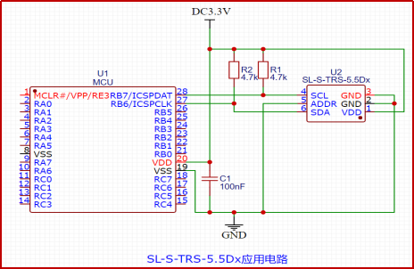
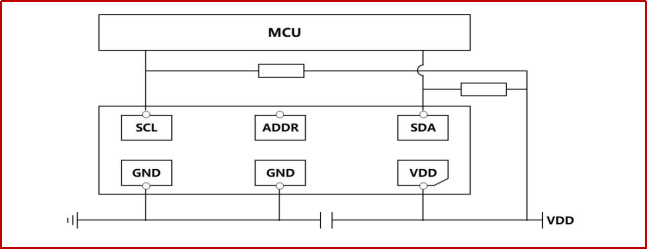
The pins of the SLKOR SL-S-TRS-5.5Dx chip include power supply, I2C bus and one address setting. The allowable range of the supply voltage is 2.5 - 5V. The data and clock lines of the I2C are pulled up. The ADDR pin is the least significant bit of the device's I2C address. If there is no need to use two sensors, it can be directly connected to GND or VCC. The sensor itself has very low power consumption. A 0.1uF capacitor between the power supply and ground is sufficient. If the sensor is relatively far from the power supply part, an additional 10uF capacitor can be considered to ensure the stability of the power supply.
2.2 The SLKOR SL-W-TRS-5.5Dx chip provides the I2C communication protocol for serial communication. The choice of the communication protocol is based on the CSB state. The I2C bus uses SCL and SDA as signal lines. Both lines are externally connected to VDDIO through pull-up resistors so that they remain at a high level when the bus is idle. The I2C chip address of SL-S-TRS-5.5D1 is shown in the following table. The least significant bit (LSB) of the 7-bit device address is determined by the SDO pin. If SDO is connected to VDDIO, the 7-bit I2C address is "1101101". If SDO is connected to GND, the 7-bit I2C address is "1101100" (as shown in the figure below).
I²C Chip Address

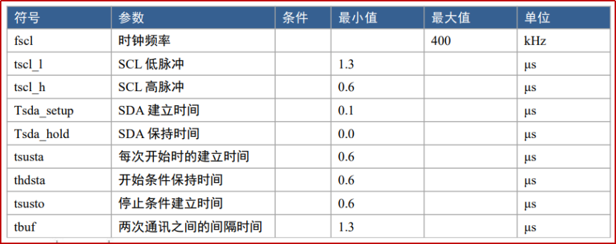
I²C Bus Line Characteristics
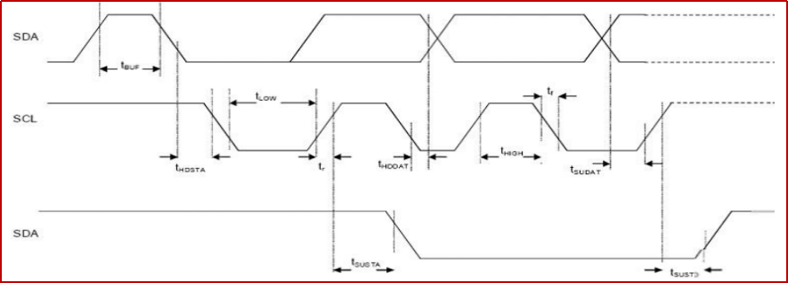
I²C Timing Diagram
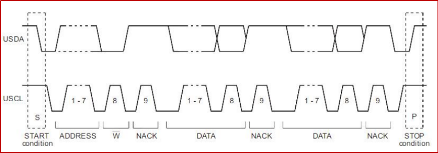
I²C Communication Protocol
2.3 When the SCL is at a high level and the SDA has a falling edge simultaneously, it marks the start of the I²C data communication. The I²C master device sends the address of the slave device (7 bits) in sequence, and then the direction control bit R/W is used to select the read or write operation. When the slave device recognizes this address, it generates an acknowledge signal and pulls the SDA low during the ninth SCL (ACK) cycle. When the SCL is at a high level and the SDA has a rising edge, it marks the end of the I²C data communication. The data transmitted on the SDA must remain stable when the SCL is high. Only when the SCL is low can the value transmitted on the SDA be changed.
3.SMD - 6P, 4.7x3.8mm Package and Dimensions
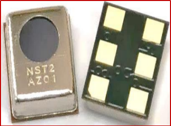
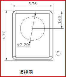

3.1 Pin Definition

Factors Affecting Temperature Measurement
4.1 Influence of Chip Consistency
For the same type of thermopile sensor, its own output characteristics are fixed. Here, "characteristics" refer to the consistent "trend" in how the chip's voltage output is affected by the environment and the temperature of the object. The differences among individual thermopile sensors lie in materials and production processes. Under the same external conditions, the absolute outputs of the sensors are not completely identical, but they can be considered to have a constant multiple relationship with each other.
4.2 Influence of Field of View (FOV)
Since the thermopile sensor is located inside the chip, there will be a window left on the chip, and an infrared filter is used as a light-transmitting window in cooperation with it. The field of view of the sensor is approximately equal to the angle formed by the intersection of the lines connecting the thermopile body on the chip cross-section and both sides of the light-transmitting window. For infrared thermopile sensors, objects within the field of view of the chip that have a temperature difference from the sensor body will affect the final output. Generally, in the application of infrared thermometers, the sensor is installed together with a metal sleeve, and lenses or light-concentrating cups are used inside to converge infrared light onto the sensor. The function of the metal sleeve is to provide a stable environmental temperature for the sensor and cooperate with the optical design to make the thermometer have a specified field of view. For non-wearable devices with sufficient space, it is recommended to ground the bottom and sides of the sensor during the design process and add a metal light cup to increase the heat capacity of the sensor, reduce the field of view, and extend the temperature measurement distance. If it is a space-constrained wearable device, the sensor can be arranged 2 - 3mm away from the outer casing according to the specific product form. When the field of view is satisfied, the opening can be designed in a basin shape. It should be noted that ordinary visible light lenses generally do not transmit far infrared light. The sensor itself is sealed. If an overall sealed design is required, it can be sealed with foam or by using infrared-transmitting silicon filters (lenses made of the same material as those on the sensor, and the square ones have a lower procurement cost). If it is necessary to change the field of view of the temperature measurement structure and metal sleeves are not allowed in the structure, the temperatures of non-measured objects within the field of view need to be taken into consideration. In some cases, the desired temperature measurement results can be obtained through compensation.
4.3 Influence of Temperature Measurement Distance
Since the intensity of infrared radiation is inversely proportional to the distance from the object, for measurement accuracy, generally, applications of forehead thermometers will require measurement within a certain distance (3 - 5cm). Especially when infrared sensors are used for close-range body temperature measurement, as the distance from the skin is very close, the distance factor has a great impact on the sensor output. Therefore, special calibration and testing are usually required.
4.4 Influence of Temperature Stability
Since the general temperature measurement and the measurement of the sensor's output voltage are completed in steps, each conversion takes a long time, and the sensor has a certain response time. Therefore, if the environmental temperature is not stable during the measurement process, the obtained temperature and the output voltage are not synchronized, which will lead to differences between the measurement result and the actual temperature value. Therefore, the stability of the sensor body temperature is also particularly important. If the structure allows, it is best to use metal components on or around the sensor to increase thermal stability.
5. Design Precautions
In application design, the key points that need to be understood are the material of the measurement object (liquid, solid, or human body), the measurement distance, and the measurement temperature range. Algorithm optimization and development should be carried out according to the application environment to improve the measurement accuracy. The original chip algorithm only guarantees that the sensor has this accuracy under the conditions of thermal equilibrium and isothermal conditions (there is no temperature difference on the sensor package). If there is a temperature difference on the sensor package, the measured accuracy will be affected. Situations that can cause temperature differences on the sensor package include, for example, there are hotter (or colder) components on the bottom or side of the sensor, or the sensor is very close to the measured object, and the measured object will locally heat the sensor.


Site Map | 萨科微 | 金航标 | Slkor | Kinghelm
RU | FR | DE | IT | ES | PT | JA | KO | AR | TR | TH | MS | VI | MG | FA | ZH-TW | HR | BG | SD| GD | SN | SM | PS | LB | KY | KU | HAW | CO | AM | UZ | TG | SU | ST | ML | KK | NY | ZU | YO | TE | TA | SO| PA| NE | MN | MI | LA | LO | KM | KN
| JW | IG | HMN | HA | EO | CEB | BS | BN | UR | HT | KA | EU | AZ | HY | YI |MK | IS | BE | CY | GA | SW | SV | AF | FA | TR | TH | MT | HU | GL | ET | NL | DA | CS | FI | EL | HI | NO | PL | RO | CA | TL | IW | LV | ID | LT | SR | SQ | SL | UK
Copyright ©2015-2025 Shenzhen Slkor Micro Semicon Co., Ltd