Service hotline
+86 0755-83044319
release time:2024-03-11Author source:SlkorBrowse:14494
GD32 is a single chip microcomputer developed in China. It is said that the developer is from ST Company, and GD32 is also made with STM32 as a template. Therefore, GD32 and STM32 are the same in many places.However, GD32 is a different product after all, and it is impossible to follow STM32 for everything. Some self-developed products are still different.We won't talk about the same places. Here are the different places.
1. Core
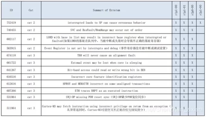
GD32 adopts the second generation M3 kernel, while STM32 mainly adopts the first generation M3 kernel. The following figure shows the M3 kernel errata of ARM, and the kernel used by GD is only one BUG, 752419.

2. Basic frequency
Use of HSE (High Speed External Clock): the maximum frequency of GD32 is 108M, and the maximum frequency of STM32 is 72M.Use HSI (High Speed Internal Clock): the maximum frequency of GD32 is 108M, and the maximum frequency of STM32 is 64M.Large frequency means that the single-chip computer code will run faster. GD is a good choice if you need to brush the screen, calculate the square root and control the motor in the project.
3. Supply electricity
External power supply: the external power supply range of GD32 is 2.6~3.6V, and that of STM32 is 2 ~ 3.6V. The power supply range of GD is relatively narrower than that of STM32.
Core voltage: GD32 core voltage is 1.2V, STM32 core voltage is 1.8V. The core voltage of GD is lower than that of STM32, so the power consumption of GD chip is lower when running.
4. Flash difference
The Flash of GD32 is independently developed, which is different from that of STM32.
GD Flash execution speed: the waiting period of program execution in GD32 Flash is 0.Execution speed of STM32 Flash: ST system frequency does not access the relation of flash waiting time, 0 waiting period, when 0 < sysclk < 24mhz; 1 waiting period, when 24mhz < sysclk ≤ 48mhz; 2 waiting period, when 48MHz<SYSCLK≤72MHz.
Flash Erase Time: GD takes a little longer to erase. The official data is as follows: "GD32F103/101 series flash models with 128 KB and below, the typical value of Page Erase is 100ms, and the actual measurement is about 60ms." The typical value of corresponding ST product Page Erase is 20~40ms.
5. Power consumption
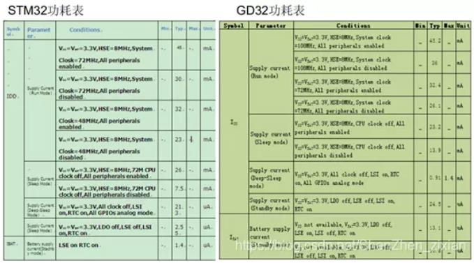
It can be seen from the following table that the operating power consumption of GD products is lower than that of STM32 under the same main frequency, but the shutdown mode, standby mode and sleep mode of GD are still higher than that of STM32 under the same settings.

6. serial port
When GD continuously sends data, there will be a Bit Idle between every two bytes, but STM32 does not, as shown in the following figure.

The serial port of GD has only 1/2 stop bit modes when sending. STM32 has four stop bit modes of 0.5/1/1.5/2.
These two differences between GD and STM32 USART have little effect on communication, but the communication time of GD will be a little longer.
7. ADC difference
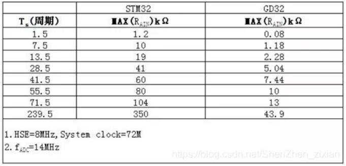
The setting of GD's input impedance and sampling time is different from ST's, and the input impedance of GD sampling with the same configuration is relatively small. See the following table for details. This is the relationship between the input impedance and the sampling period when the ADC runs at the main frequency of 72M and the sampling clock of 14M:

8. FSMC
Only the large capacity (256K and above) above 100Pin of STM32 has FSMC, and all those above 100Pin of GD32 have FSMC.
9. 03 Series RAM&FLASH Size Difference
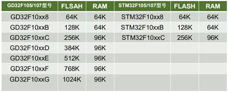
The ram and flash pairs of GD103 series and ST103 series are as follows:

10. Differences between 105-107 series STM32 and GD
There are many more choices of GD's 105/107 than ST's. See the following table for details:

11 capacity of resisting disturbance
On this point, the official didn't give it, and the author discovered it by accident while doing the project.
Originally, STM32F103C8T6 was used in the project, and later it was replaced by GDF103C8T6. The pins of the two chips are completely consistent. The single-chip microcomputer uses two adjacent pins as the clock pins and data output pins of SPI, and then finds that the SPI of STM32 can communicate normally, but that of GD can't. After inspection, it is found that there are two IIC copper wires passing through the back of the copper wire of SPI of PCB board, and the signal should be affected.
Looking at the pin level with an oscilloscope, it is found that the waveforms of data pins of STM32 and GD are abnormal, but the waveforms of STM32 are much better. Although the waveforms are a little worse, SPI communication is still normal. And GD can't communicate normally.
Then the author slowed down the communication rate of SPI, and found that the data pin of STM32 quickly returned to normal waveform, while that of GD was still poor, and it didn't return to normal until the rate dropped to a very low level. Initially, it is suspected that STM32 has some circuits to filter the pins, but GD does not.
Although the wiring of the used circuit board itself is somewhat unreasonable, in the same harsh environment, STM32 still ensures the normal communication, but GD can't, which shows that GD's anti-interference ability is inferior to STM32 to some extent.


Site Map | 萨科微 | 金航标 | Slkor | Kinghelm
RU | FR | DE | IT | ES | PT | JA | KO | AR | TR | TH | MS | VI | MG | FA | ZH-TW | HR | BG | SD| GD | SN | SM | PS | LB | KY | KU | HAW | CO | AM | UZ | TG | SU | ST | ML | KK | NY | ZU | YO | TE | TA | SO| PA| NE | MN | MI | LA | LO | KM | KN
| JW | IG | HMN | HA | EO | CEB | BS | BN | UR | HT | KA | EU | AZ | HY | YI |MK | IS | BE | CY | GA | SW | SV | AF | FA | TR | TH | MT | HU | GL | ET | NL | DA | CS | FI | EL | HI | NO | PL | RO | CA | TL | IW | LV | ID | LT | SR | SQ | SL | UK
Copyright ©2015-2025 Shenzhen Slkor Micro Semicon Co., Ltd