Service hotline
+86 0755-83044319
release time:2023-09-11Author source:SlkorBrowse:13195
Although some may consider IGBT as "conventional" technology, it still plays a significant role in high-power applications.
Today, most news and discussions in the semiconductor industry revolve around devices based on new wide-bandgap (WBG) materials such as silicon carbide (SiC) and gallium nitride (GaN). However, just a few years ago, the preferred solution for many applications was the Insulated Gate Bipolar Transistor (IGBT).
There is still a presence of medium to high-power applications that utilize IGBTs, and the devices themselves continue to evolve. In this article, we will delve into the details of IGBTs and explore their existing and emerging applications.
IGBT: Physical Structure
IGBT is a semiconductor transistor or switch composed of four alternating layers of semiconductor materials (PNPN). When the correct voltage is applied to the device's gate, it allows current to flow—this conduction stops when the voltage is removed.
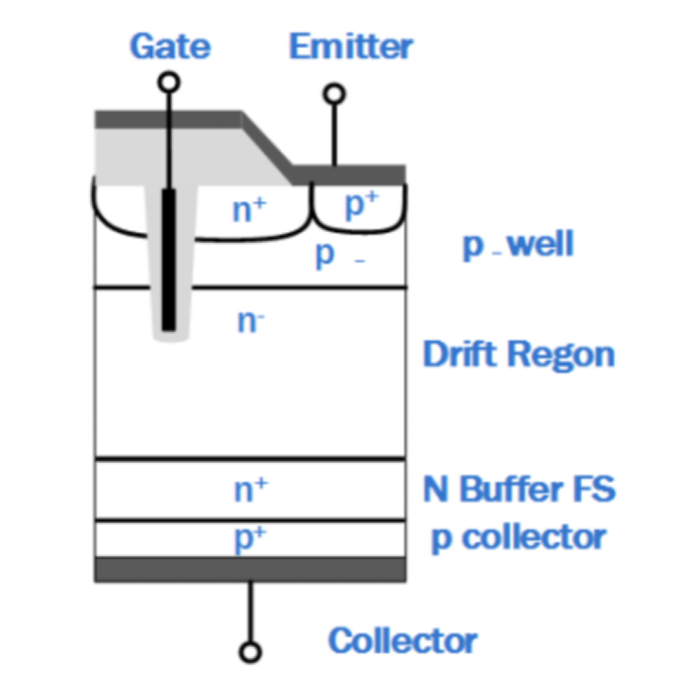
Since its inception, IGBT has undergone continuous refinement and improvement, particularly in reducing switching losses and creating thinner structures. Nowadays, IGBTs commonly incorporate a trench gate combined with a field stop structure as a means to suppress parasitic NPN characteristics within the device. Once achieved, conduction losses and saturation voltage are reduced, resulting in benefits such as increased power density.

Figure 1: Structure of Field-Stop IGBT with Trench Channel Cutoff
IGBT Utilization and Technical Examples
IGBT finds wide applications in various fields, including solar inverters, energy storage systems, uninterruptible power supplies (UPS), motor drives, electric vehicle chargers, industrial welding, and household appliances. Typically, the topology structure is chosen specifically to meet the requirements of a particular application. Let's compare and contrast some popular applications.
Industrial Welding
Considering the demand for higher-quality welding, it requires precise control over the welding process. Therefore, inverters are commonly used instead of typical welding transformers because DC output current can achieve the necessary accuracy.
There is also a safety aspect since DC current is generally considered safer. From the user's perspective, inverters are smaller and lighter compared to transformers, making welding machines more portable and convenient to use.
In a typical welding machine, single-phase or three-phase AC power is rectified to form the DC bus voltage. The rectifier also powers the small converters that generate the voltage required by the control unit. The DC bus voltage powers the inverter, which typically has a nominal output voltage of around 30 VDC. However, during operation, under open-circuit load conditions, the voltage may double and drop to almost 0V (actually short-circuit) when triggering the welding arc."

Figure 2: Overview of a Typical Welding Machine
Many different topology structures are suitable for inverter-based welding machines. However, the most common ones include Full Bridge (FB), Half Bridge (HB), and Two-Switch Forward. In FB and HB topologies, the switching frequency is typically in the range of tens of kHz, usually around 20 - 50 kHz. The duty cycle is controlled based on the load level and output voltage. In terms of control schemes, it is often constant current.

Figure 3: Common topologies include FB, HB, and Two-Switch Forward
Industrial Motor Drivers
One of the most common industrial applications is industrial motor drivers, which can be used for robots, large machinery, or many other motion-dependent applications. Most motor driver applications are configured as HB, with frequencies between 2 kHz and 15 kHz. The resulting output voltage depends on the switch status and current polarity.

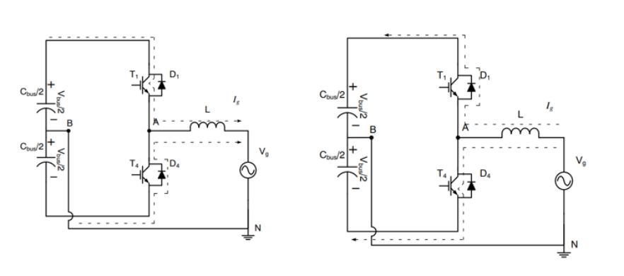
Figure 4: Half Bridge Topology displaying positive and negative output current.
The motor is an inductive load, so the current increases rapidly. When positive current flows (Ig > 0), the high-side transistor (T1) turns on and delivers energy to the load (Vg). However, if the load current Ig flows in the opposite direction (negative polarity), the current flows back through D1, returning the energy to the DC source.
If the low-side transistor conducts (T4 is on) and the high-side transistor (T1) is off, a voltage equal to half of Vbus (-Vbus/2) is applied to the load, reducing the current. If Ig is greater than zero, the current flows through D4, returning the energy to the bus source.
To be continued...


Site Map | 萨科微 | 金航标 | Slkor | Kinghelm
RU | FR | DE | IT | ES | PT | JA | KO | AR | TR | TH | MS | VI | MG | FA | ZH-TW | HR | BG | SD| GD | SN | SM | PS | LB | KY | KU | HAW | CO | AM | UZ | TG | SU | ST | ML | KK | NY | ZU | YO | TE | TA | SO| PA| NE | MN | MI | LA | LO | KM | KN
| JW | IG | HMN | HA | EO | CEB | BS | BN | UR | HT | KA | EU | AZ | HY | YI |MK | IS | BE | CY | GA | SW | SV | AF | FA | TR | TH | MT | HU | GL | ET | NL | DA | CS | FI | EL | HI | NO | PL | RO | CA | TL | IW | LV | ID | LT | SR | SQ | SL | UK
Copyright ©2015-2025 Shenzhen Slkor Micro Semicon Co., Ltd