Service hotline
+86 0755-83044319
release time:2023-09-11Author source:SlkorBrowse:9065
Modern Induction Cooktops
Induction cooking has replaced traditional heating by transferring heat energy to the bottom of a pan/pot through electric heating elements. It operates based on the principle of induced currents circulating within the bottom of the pot. For induction cooktops to function properly, the pot's bottom must be physically close to the coil, and only certain metals are suitable - those with high magnetic permeability.
The principle is similar to common power transformers, with the coil as the primary and the pot's bottom as the secondary. It shares many similarities with modern induction charging technology as well.
The heat required for heating the pot comes from the eddy currents circulating in the bottom layer or, more specifically, from the resistance offered by these current flows. Through inductive coupling, approximately 90% of the energy is transferred to generate heat in the pot. A typical smooth glass-top stove can only transmit about 70% of the energy, resulting in a threefold reduction in losses.
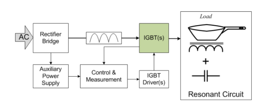
The topology used is not significantly different from a welding circuit. The main AC power is rectified and drives a small auxiliary power supply for the inverter and controller. The inverter induces the current into copper coils, creating an electromagnetic field that induces eddy currents in the pot. The generated heat is equal to the resistance of the pot's bottom multiplied by the square of the induced current - known as the "Joule effect

Figure 5: Overview of a Typical Induction Cooktop Circuit
Unlike welding machines, the control scheme for induction cooktops is typically a frequency variation scheme. While this is a simple method, the challenge lies in controlling the required frequency range for output power over a wide range.
Even at the high frequencies required for induction cooktops, resonant converter circuits can operate with high efficiency. Therefore, resonant circuit converters are commonly used for this application, especially resonant half-bridge (RHB) converters and quasi-resonant (QR) inverters. RHB converters are particularly favored due to their ability to handle a wide range of loads. Advanced control techniques such as zero-current switching (ZCS) or zero-voltage switching (ZVS) are typically employed to keep power losses to a minimum.

Figure 6: Typical Examples of RHB and QR Topologies
Due to the cost-effectiveness of this topology, QR converters are often used in low-power (below 2W peak power) induction cooktop applications.
Solar inverters and UPS
When using the half-bridge topology in applications that require fast switching, there are many challenges, including:
- Only two output voltages can be achieved
- Switching losses can be significant
- Driving the large gates can be challenging
- Component stress affects reliability
- Increased ripple current and EMI require extensive filtering
- Incompatible with high-voltage DC bus
- Thermal design is not trivial
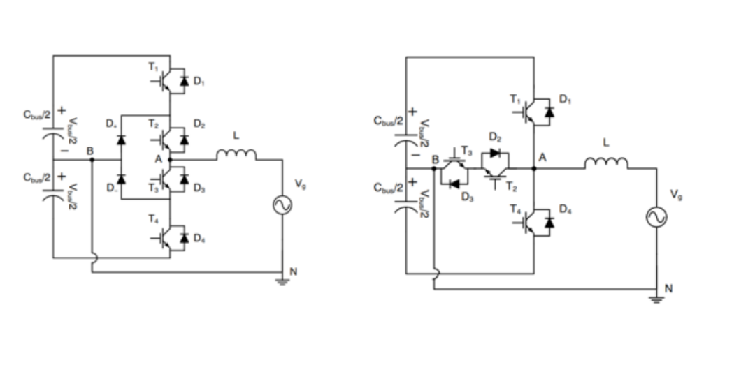
In modern applications, the HB topology is being replaced by critical applications such as Uninterruptible Power Supplies (UPS) and solar photovoltaic (PV) inverters. Three-level topologies are becoming dominant, known as I-Type and T-Type.
There are many aspects that need improvement, including reducing the voltage across the active devices to lower losses, reduce harmonic distortion, and allow for the use of smaller components. Most importantly, these topologies can significantly reduce switching losses, achieving efficiency up to 98% when switching at high frequencies ranging from 16 kHz to 40 kHz.

Figure 7: I-Type and T-Type Converter Topologies have many advantages compared to HB
Looking to the Future
Although some may view IGBT technology as "traditional," it still plays an important role in high-power (high voltage/current) applications. IGBT technology continues to evolve, with Vcesat values approaching 1V, and structural improvements increasing density and reducing losses.
As always, when using IGBTs, designers must have a full understanding of their application requirements and select appropriate topologies to ensure optimal results and performance.


Site Map | 萨科微 | 金航标 | Slkor | Kinghelm
RU | FR | DE | IT | ES | PT | JA | KO | AR | TR | TH | MS | VI | MG | FA | ZH-TW | HR | BG | SD| GD | SN | SM | PS | LB | KY | KU | HAW | CO | AM | UZ | TG | SU | ST | ML | KK | NY | ZU | YO | TE | TA | SO| PA| NE | MN | MI | LA | LO | KM | KN
| JW | IG | HMN | HA | EO | CEB | BS | BN | UR | HT | KA | EU | AZ | HY | YI |MK | IS | BE | CY | GA | SW | SV | AF | FA | TR | TH | MT | HU | GL | ET | NL | DA | CS | FI | EL | HI | NO | PL | RO | CA | TL | IW | LV | ID | LT | SR | SQ | SL | UK
Copyright ©2015-2025 Shenzhen Slkor Micro Semicon Co., Ltd